
Page 104 - Catalogue 2019
P. 104
LUG TYPE PROCESS VALVE T 214-C LUG TYPE PROCESS VALVE T 214-C
TECHNICAL DATA TORQUE
Nominal diameter: DN (40)50 - DN 300 - The torque values specifi ed
(Md) are based on dry media
Face-to-face: EN 558 Table 20 and are measured with air at
a temperature of 20 °C
Flange
accommodation: EN 1092 PN 10/16 - The values specifi ed are based DN (mm) 40/50 65 80 100 150 200 250 300
ASME Class 150 on the initial breakaway torque Size (in) 1½ 2 2½ 3 4 6 8 10 12
Flange Surface (disc disengages from seat,
Design: EN 1092 Form A/B torque then drops) MD (Nm) 35 35 55 70 135 170 320 380
ASME RF, FF MAST (Nm)* 105 105 250 250 480 480 1020 1020
- Dynamic torque specifi cation *Maximum torques (Nm)
Top fl ange: EN ISO 5211 available upon request
Marking: EN 19 Regarding the dimensioning of
PAS 1085 actuators, please contact our 18
engineers. 16 DN 50 - 150 special design, installation between fl anges
Tightness check: EN 12266 (Leakage rate A)
Temperature range: -40°C to +200°C 14
(depending on working pressure) 12
Operating pressure: max. 10 bar (16 bar special version) 10 DN 50 -300, installation between fl anges
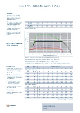
Vacuum: up to1 mbar absolute, PRESSURE/TEMPERA- System Pressure PS (bar) 8
(with silicon elastomer inserts) TURE DIAGRAM 6 DN 50 - 150, end of line service
from -10°C to +160°C 4 DN 200 - 300, end of line service
Valve Design 2
0
PTFE-lined lug type valve for chemically toxic and highly
corrosive media. acc. to PAS 1085 -40 -20 0 20 40 60 80 100 120 140 160 180 200
System Temperature TS (°C)
Service limitation with Fluor carbon inserts (FPM) from -10°C up to +120°C
FEATURES Pressure-Temperature-Diagram for valves with Silicone elastomer inserts
Service limitation with EPDM elatomer inserts from -10°C up to +180°C
- Environmental protection via EBRO-Safety seal Vacuum service to 1mbar absolute, from -10°C up to +160°C. Valve installation between fl anges
- TA-Luft/ VDI 2440,RWTÜV certifi ed
- Isolation height according to plant prescription K -VALUES DN Size Opening angle α°
v
- Maintenance-free - The K -value [m³ per hour] is the [mm] [in] 20° 30° 40° 50° 60° 70° 80° 90°
v
- Can be disassembled, material-specifi c recycling possible fl ow of water at a temperature of 1) K v -values metal disc
5°C to 30°C (41°F to 86°F) at
- Material conform to FDA to EG 1935/2004 ∆p of 1 bar 40/50 1½ 2 4 5 16 35 57 81 101 114
65 2½ 5 8 25 56 99 153 216 287
- The K -values specifi ed are 80 3 13 12 30 69 131 216 328 467
v
based on tests carried out by the 100 4 13 25 61 121 207 319 459 627
Delfter Hydraulics Laboratories,
DESIGN FEATURES the Netherlands 150 6 50 94 171 303 509 810 1226 1778
200 8 137 149 344 696 1178 1764 2426 3137
- Optimized low torques 1 - Permissible velocity of fl ow 250 10 178 291 562 1021 1699 2626 3832 5348
Vmax 4,5 m/s for liquids,
- FEM dimensioned componets 2 Vmax 70 m/s for gases 300 12 395 378 820 1638 2751 4079 5538 7049
v
- Double fl at shaft acc. to EN standards 2) K -values PFA-disc
- The throttle function is linear at 40/50 1½ 2 2 4 13 25 40 53 63 66
- Shaft/ disc: duplex (one-piece lost-wax casting)
an angle 30° to 70° 65 2½ 3 9 26 48 74 98 117 126
- Triple shaft bearing
- Avoid cavitation 80 3 4 14 38 71 108 143 171 186
100 4 6 16 48 95 151 209 262 303
For further values, please contact 150 6 18 60 161 317 526 787 1096 1452
Safety seal at both shaft ends: our engineers. 200 8 125 176 395 756 1234 1807 2449 3136
1.Primary sealing by means of a belleville spring washer, trans- 250 10 138 333 644 1103 1744 2599 3702 5086
mitting prestress on the spherical segment area. 300 12 203 462 872 1479 2329 3471 4950 6814
2.Secondary sealing of the shaft by means of PTFE-Chevron and
o-ring. Subject to change without notice
post@ebro-armaturen.com
T 214-C 2.5 www.ebro-armaturen.com
01.2019