
Page 109 - Catalogue 2019
P. 109
53310_Reg-QM-High-d 17.10.2005 10:35 Uhr Seite 4
53310_Reg-QM-High-d 17.10.2005 10:35 Uhr Seite 4
QUALITÄTSMERKMALE
QUALITÄTSMERKMALE
HIGH PERFORMANCE KLAPPEN
HIGH PERFORMANCE KLAPPEN
DIE PRODUKTVORTEILE IM ÜBERBLICK
DIE PRODUKTVORTEILE IM ÜBERBLICK
HIGH PERFORMANCE BUTTERFLY VALVE HP 111
HIGH PERFORMANCE BUTTERFLY VALVE HP 111 HIGH PERFORMANCE BUTTERFLY VALVE HP 111 Die doppelexzentrische Bauweise bietet dort Vorteile,
Die doppelexzentrische Bauweise bietet dort Vorteile,
wo hohe Druck- und Temperaturbelastungen herrschen.
wo hohe Druck- und Temperaturbelastungen herrschen.
Kopfflanschausführung nach EN ISO 5211
Kopfflanschausführung nach EN ISO 5211
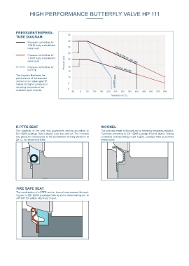
Druck-Temperatur Diagramm HP
Einteiliges Gehäuse mit Überfahrsicherung.
Einteiliges Gehäuse mit Überfahrsicherung.
MATERIAL SPECIFICATION AND PARTS LIST PRESSURE/TEMPERA- 45
Die durchgehende Welle sorgt für höchste Biegefestigkeit.
TURE DIAGRAM
G 17 21 22 Die durchgehende Welle sorgt für höchste Biegefestigkeit.
H 1 Flange 8 Pressure control line for 40
Bei allen Nennweiten werden wartungsfreie, überlange
Bei allen Nennweiten werden wartungsfreie, überlange
G
1.0619 body material and
20 korrosions- und temperaturbeständige Lager eingesetzt
korrosions- und temperaturbeständige Lager eingesetzt
35
metal seat
zur exakten Zentrierung der Klappenscheiben.
zur exakten Zentrierung der Klappenscheiben.
F 14
H 1 Pressure control line for 30
Der federunterstützte R-PTFE-Sitzring gewährleistet abso-
Der federunterstützte R-PTFE-Sitzring gewährleistet abso-
10 7 24 1.4408 body material and
Pressure (bar)
25Sitzringaustausch
lute Dichtheit und gleicht Verschleiß aus. Sitzringaustausch
23 lute Dichtheit und gleicht Verschleiß aus.
metal seat
ohne Demontage von Welle und Klappenscheibe möglich.
PN 40 (DN 50 - DN 150)
Version with fitting key 16 ohne Demontage von Welle und Klappenscheibe möglich.
for valves ≥ DN 700 2 18 Klemmring schützt Sitzring vor Abrasion und Erosion. PN 25 (> DN 150)
18
Pressure control line for
Klemmring schützt Sitzring vor Abrasion und Erosion.
19 9 4 R-PTFE 15
A 1
5 6
The diagram illustrates the
Kraftschlüssige Verbindung zwischen Scheibe und Welle
Kraftschlüssige Verbindung zwischen Scheibe und Welle
19 29 28 performance of the standard 10
und geringe Abscherspannungen durch tangential ange-
und geringe Abscherspannungen durch tangential ange-
version of our valve type HP. R-PTFE-seat
ordnete Keilstifte.
ordnete Keilstifte.
3 Valves for higher pressure or 5
ØD Z 1
C Z 2 15 deviating temperature are
Gehärtete Lagerringe für exakte Zentrierung der Klappen-
Gehärtete Lagerringe für exakte Zentrierung der Klappen-
0
available upon request.
scheibe.
25 scheibe. -50 0 50 100 150 200 250 300 350 400 450 500 550 600
11 Temperature (°C)
Doppelexentrische Klappenscheibe bewirkt niedriges
B 9 26 Doppelexentrische Klappenscheibe bewirkt niedriges
Drehmoment und verringert den Verschleiß.hleiß.
Drehmoment und verringert den Versc
Alle Dichtflächen sind mechanisch feinst bearbeitet.
6 Alle Dichtflächen sind mechanisch feinst bearbeitet.
27
13 Selbstnachdichtende Wellenabdic
Selbstnachdichtende Wellenabdichtunghtung
E 29 28 12 Pts. 25-27:
Cover plate for
HP 111 with bare shaft end acc. to EN ISO 5211 valve ≥ DN 350
R-PTFE SEAT INCONEL
Dimensions [mm] Pt. Description Material Material No. ASTM Pt. Description Material Material No. ASTM The elasticity of the seat ring guarantees sealing according to The seat ring made of Inconel and is extremely temperaturestable.
DN Size min. Weight 1 Body 14 Shaft seal EN 12266,Leakage Rate A (tight): Leak test with air. The constant Tightness according to EN 12266 Leakage Rate B (tight): Testing
[mm] [in] A B C D E F Flange G H1 Z1 Z2 pipe-Ø [kg] Carbon Steel GS-C25N 1.0619 WCB PTFE test pressure corresponds to the permissible working pressure at conditions corresponding to EN 12266, Leakage Rate B, but test
50-65 2-2½ 133 99 232 112 43 80 F05/F07 12 15 41 - 51 7 Stainless Steel G-X5CrNiMo19-11-2 1.4408 CF8M Graphite 20 °C, not exceeding 6 bar. media water.
80 3 142 113 255 138 46 80 F05/F07 12 15 71 54 80 8 2 Disc 15 Hex.-socket screw
100 4 158 124 282 160 52 80 F05/F07 12 15 94 82 103 9 3 Stainless Steel G-X5CrNiMo19-11-2 1.4408 CF8M 16 Stainless Steel A4-70 1.4401 B8M
Threaded pin
Clamping ring
125 5 181 140 321 192 56 80 F07/F10 14 18 115 105 124 13 Stainless Steel G-X5CrNiMo19-11-2 1.4408 CF8M Stainless Steel A2-70 1.4301 B 8
150 6 195 154 349 216 56 80 F07/F10 14 18 144 135 151 15 Stainless Steel X2CrNiMo17-12-2 1.4404 316 L 17 Hex. nut
200 8 225 191 416 270 60 80 F10/F12 17 18 187 181 196 23 Steel St37-2 1.0037 Stainless Steel A 2 1.4301 8
250 10 268 222 490 326 68 80 F10/F12 22 23 235 229 245 34 4 Shaft 18 Spacer sleeve
300 12 300 255 555 378 78 90 F12 27 28 281 276 296 48 Stainless Steel (< 300°C) X4CrNiMo16-5-1 1.4418 19 Stainless Steel X6CrNiMoTi17-12-2 1.4971 316 Ti
Graphite seal (for metal seat)
Stainless Steel (> 300°C) X6NiCrTiMoVB 25-15-2 1.4980
350 14 345 304 649 438 92 100 F14 27 28 323 316 334 95 Stainless Steel X5CrNiCuNb16-4 1.4542 Graphite
400 16 375 339 714 488 102 100 F16 36 36 372 364 385 115 5 Seat ring 20 Belleville spr. washer
450 18 412 340 752 530 114 120 F16 36 36 427 427 438 141 R-PTFE PTFE-Compound Stainless Steel X10CrNi18-8 1.4310 301 Ti
500 20 425 399 824 593 127 120 F16 46 46 469 466 484 186 Inconel Inconel 625 21 Bracket St37-2 galvanized 1.0037 283-C
PTFE/Inconel 625
FireSafe
Steel
550 22 456 405 861 635 154 200 F25 46 46 526 526 540 236 6 Shaft bearing 22 Hex. bolt R-PTFE Sitz INCONEL
INCONEL
R-PTFE Sitz
600 24 490 468 958 692 154 200 F25 55 55 544 542 560 310 Stainless Steel X6CrNiMoTi17-12-2 1.4571 nitrite 316 Ti Steel St galvanized CS FIRE SAFE SEAT
700 28 554 522 1076 820 165 200 F25 80 130 673 659 678 430 7 Gland flange 23 Hex. nut Die Elastizität des Sitzrings gewährleistet die Abdichtung Der Sitzring aus Inconel ist extrem temperaturbeständig.
The combination of a PTFE and an Inconel seat ensures the seal-
Der Sitzring aus Inconel ist extrem temperaturbeständig.
Die Elastizität des Sitzrings gewährleistet die Abdichtung
ing acc. to EN 12266 (Leakage Rate A) and a metal sealing acc. to
750 30 569 535 1104 857 965 165 200 F30 80 130 711 - 510 Stainless Steel X5CrNi18-10 1.4301 304 Steel St galvanized CS nach EN 12266, Leckrate 1 (dicht). Dichtigkeit nach EN 12266, Leckrate 1 (dicht).
nach EN 12266, Leckrate 1 (dicht).
Dichtigkeit nach EN 12266, Leckrate 1 (dicht).
800 32 605 566 1171 902 190 200 F30 90 130 748 736 776 551 8 Stainless Steel G-X5CrNiMo19-11-2 1.4408 CF8M 24 Washer St galvanized CS API 607 5th edition after heat impact.
Steel
Thrust collar
900 36 660 637 1297 1006 204 200 F30 100 145 847 833 876 732 Stainless Steel X5CrNi18-10 1.4301 304 25 Seal
1000 40 715 687 1402 1112 216 200 F30 100 145 944 935 975 802 9 Bearing ring Graphite
1200 48 815 800 1615 1328 200 F35 110 185 1139 1135 1175 1300 Stainless Steel X6CrNiMoTi17-12-2 1.4571 chr-pld 316 Ti 26 Cover plate
Subject to change without notice 10 Suppor. washer Steel St37-2 galvanized 1.0037 283-C
Stainless Steel X6CrNiMoTi17-12-2 1.4571 316 Ti Stainless Steel G-X5CrNiMo19-11-2 1.4408 CF8M
11 Taper pin 27 Hex.-socket screw
Stainless Steel X4CrNiMo16-5-1 1.4418 Stainless Steel A2-70 1.4301 B 8
12 Plug screw DIN 908 28 Centering piece
Stainless Steel G-X5CrNiMo19-11-2 1.4408 CF8M Stainless Steel X6CrNiMoTi17-12-2 1.4571 316 Ti
13 Seal 29 Countersunk screw
PTFE Stainless Steel A 2 1.4301 SS
Graphite Other materials upon request
Subject to change without notice