
Page 129 - Catalogue 2019
P. 129
HIGH PERFORMANCE BUTTERFLY VALVE HP 114-C HIGH PERFORMANCE BUTTERFLY VALVE HP 114-C
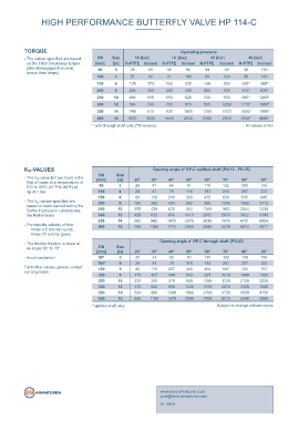
TECHNICAL DATA TORQUE Operating pressure
Nominal diameter: DN 80 - DN 400 - The values specifi ed are based DN Size 10 [bar] 16 [bar] 25 [bar] 40 [bar]
on the initial breakaway torque. [mm] [in] R-PTFE Inconel R-PTFE Inconel R-PTFE Inconel R-PTFE Inconel
Face-to-face: EN 558 Table 25 (disc disengages from seat, 80 3 28 55 30 65 34 90 38 100
torque then drops)
100 4 51 90 61 100 80 120 95 140
Design: Lug type
(optional: through holes) 150 6 125 170 136 220 168 300 220* 360*
200 8 205 350 260 430 280 505 315* 630*
Body: 1.0619 (WCB); 1.4408 (CF8M) 250 10 485 505 550 620 600 860 685* 1260*
Temperature range: -60°C to +230°C (R-PTFE-Seat) 300 12 584 740 700 970 855 1280 1115* 1800*
-60°C to +600°C (Inconel-Seat) 350 14 740 815 930 1050 1200 1370 1650* 1900*
400 16 1150 1530 1640 2240 2460 2900 3830* 4000*
Nominal pressure: max. 40 bar
* with through shaft only (TS-version) All values in Nm
Leakage rate: R-PTFE, EN 12266, Leakage rate A
Inconel, EN 12266, Leakage rate B
Flange drilling: EN 1092 PN 10/16/25/40
Marking: EN 19
PAS 1085
TA-Luft
K -VALUES Opening angle α° HP-C splitted shaft (PN 10 - PN 25)
v
DN
- The K -value [m³ per hour] is the [mm] Size 20° 30° 40° 50° 60° 70° 80° 90°
v
[in]
fl ow of water at a temperature of
5°C to 30°C (41°F to 86°F) at 80 3 20 41 65 91 110 132 150 156
∆p of 1 bar 100 4 24 41 78 118 183 241 287 323
815
88
845
638
High Performance valve for the chemical industry. - The K -values specifi ed are 150 6 8 194 150 215 320 475 1335 1666 1712
Valve Design based on tests carried out by the 250 10 255 430 1410 1413 1369 1852 2344 2430
v
955
286
662
434
200
acc. to PAS 1085
924
620
Delfter Hydraulics Laboratories,
300
3788
930
632
429
3622
2052
2870
12
the Netherlands
14
942
4989
4751
2916
565
2076
350
3876
- Permissible velocity of fl ow
Vmax 4,5 m/s for liquids,
Vmax 70 m/s for gases 400 16 708 1185 1772 2683 3888 5279 6812 6977
- The throttle function is linear at Opening angle α° HP-C through shaft (PN 40)
DN
FEATURES an angle 30° to 70° [mm] Size 20° 30° 40° 50° 60° 70° 80° 90°
[in]
- Plane sealing surface without interference - Avoid cavitation! 80* 3 20 41 65 91 110 132 150 156
(groove acc. to EN 1092 optional) 100* 4 24 41 78 118 183 241 287 323
For further values, please contact
- Clamping ring without bore holes our engineers. 150 6 80 170 257 345 463 587 722 757
907
8
- Long valve neck (for complete isolation) 200 10 179 307 444 643 1260 1210 1440 1460
850
570
2230
390
233
1700
250
2150
- Distortion stop outside of media fl ow
300 12 370 620 890 1330 1970 2670 3380 3500
- Integrated gland fl ange 350 14 534 890 1349 1968 2769 3735 4550 4750
- Quick and easy mounting 400 16 690 1160 1670 2500 3700 5012 6340 6580
- Can be installed in any desired position * splitted shaft only Subject to change without notice
- Maintenance-free
- Integrated primary shaft seal
- FIRE SAFE BS 6755 PART 2
GENERAL APPLICATIONS
- Chemical and petrochemical Industry
- Heavy-Duty applications Gland fl ange integrated in top fl ange.
post@ebro-armaturen.com
HP 114-C 3.5 www.ebro-armaturen.com
01.2019