
Page 137 - Catalogue 2019
P. 137
HIGH PERFORMANCE BUTTERFLY VALVE HP 114-K3 HIGH PERFORMANCE BUTTERFLY VALVE HP 114-K3
TECHNICAL DATA TORQUE Operating pressure
Nominal diameter: DN 50 - DN 600 - The values specifi ed are based DN Size 10 [bar] 16 [bar] 25 [bar] 40 [bar]
(larger nominal diameter on request) on the initial breakaway torque. [mm] [in] R-PTFE Inconel R-PTFE Inconel R-PTFE Inconel R-PTFE Inconel
(disc disengages from seat, 50-65 2-2½ 27 35 28 42 30 58 31 66
torque then drops)
Face-to-face: EN 558 Series 16 80 3 28 55 30 65 34 90 38 100
ISO 5752 Series 16 100 4 51 90 61 100 80 120 93 140
125 5 63 150 83 172 95 220 125 285
Flange accommodation: EN 1092 PN 10/16/25/40 (to DN 150)
EN 1092 PN 10/16/25 (DN 200-DN 600) 150 6 125 170 136 220 168 300 220 360
ASME Class 150/300 200 8 205 350 260 430 280 505 * *
AS 4087 PN16/21 250 10 485 505 550 620 600 860 - -
300 12 584 740 700 970 855 1280 - -
Flange Surface Design: EN 1092, Form A/B, 350 14 740 815 930 1050 1200 1370 - -
ASME RF,FF
400 16 1050 1530 1640 2240 2460 2900 - -
Top fl ange: EN ISO 5211 450 18 1150 1700 1750 2500 2700 3500 - -
500 20 1210 2010 1800 2760 2800 4260 - -
Marking: EN 19 600 24 4000 4500 4600 5740 6200 8080 - -
* DN 200 PN 16 max. 25 bar All values in Nm
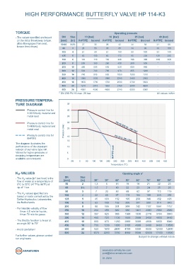
Tightness check Druck-Temperatur Diagramm HP
- for R-PTFE seat: EN 12266 (Leakage rate A) PRESSURE/TEMPERA-
- for Inconel seat: EN 12266 (Leakage rate B)
ISO 5208, Category 3 TURE DIAGRAM 45
Pressure control line for 40
Temperature range: -60°C to +600°C
1.0619 body material and
metal seat 35
Differential pressure: ≤ DN150 max. 40 bar
> DN150 max. 25 bar
Pressure control line for 30
Lug type butterfl y valve in double-eccentric construction. Reliable 1.4408 body material and PN 40 (DN 50 - DN 150)
sealing even with extreme temperature and pressure conditions. Vacuum: up to 1mbar absolute metal seat Pressure (bar) 25
Pressure control line for 18
R-PTFE PN 25 (> DN 150)
15
The diagram illustrates the
FEATURES performance of the standard 10
version of our valve type HP.
Valves for higher pressure or 5 R-PTFE-seat
- Shut-off and control of gaseous and liquid media deviating temperature are
- Disc has double-eccentric bearing available upon request. 0
250
300
L
- Centering pieces can be used as installation aid C Seat Eccentricity shaft/seat -50 0 50 100 150 200 Temperature (°C) 350 400 450 500 550 600
- Two seat ring systems available: R-PTFE and Inconel
- Seal variants: K -VALUES
soft-sealing (R-PTFE) max. 230°C v Opening angle α°
metallic sealing (Inconel) max. 600°C - The K -value [m³ per hour] is the DN Size
v
fi re safe (PTFE / Inconel) max. 200°C fl ow of water at a temperature of [mm] [in] 20° 30° 40° 50° 60° 70° 80° 90°
- Maintenance-free Eccentricity shaft/ 5°C to 30°C (41°F to 86°F) at 50 2 1,3 6 15 18 19 21 22 23
∆p of 1 bar
25
25
7
- Long service life, even at high switching frequencies centerline pipeline 65 2½ 1,5 30 18 22 23 24 113 115
82
50
97
80
3
7
68
- Fire safe BS 6755 Part 2, API 607 5th Edition - The K -values specifi ed are
v
based on tests carried out by the 100 4 22 60 97 119 164 199 223 251
GENERAL APPLICATIONS Delfter Hydraulics Laboratories, 125 5 45 100 152 195 256 346 452 493
the Netherlands
C Pipeline 150 6 63 109 162 250 391 588 814 845
L
- Chemical and petrochemical industries - Permissible velocity of fl ow 200 8 96 168 301 509 742 1107 1581 1747
- Hot water and steam systems Vmax 4,5 m/s for liquids, 250 10 264 458 682 980 1421 2083 2882 2889
Vmax 70 m/s for gases 300 12 397 625 956 1368 1938 2778 3794 3940
- District heat supply 350 14 460 720 1100 1650 2500 3400 4800 5400
- Vacuum systems - The throttle function is linear at 400 16 550 870 1250 2000 3200 4800 6800 8080
- Shipbuilding an angle 30° to 70° 450 18 730 1200 1800 3100 4600 6400 8400 10500
- Gas process technology - Avoid cavitation! 500 20 920 1600 2600 4100 6000 8500 12100 12800
- Food industry 600 24 1370 2250 3780 4950 9000 12500 17100 18500
For further values, please contact
- Heavy duty services our engineers. Subject to change without notice
post@ebro-armaturen.com
HP 114-K3 3.7 www.ebro-armaturen.com
01.2019