
Page 190 - Catalogue 2019
P. 190
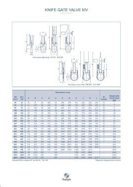
KNIFE GATE VALVE MV                                                                                             FLANGE DRILLINGS MV


                                                                                                                                          DN 50 - DN  65  DN 80 - DN 200  DN 25 0 - DN  300  DN 350 - DN  400  DN  450 - DN  600


                               One piece valve body: DN 50 - DN 800


                                                                                                                                                      DN 7 00 - DN  800  DN 9 00 - DN 1 000     DN 1200
                                                                Two piece valve body: DN 900 - DN 1600                        ● = Tapped holes  ○= Throughgoing holes

                                                                                                                            FLANGE DRILLING ACCORDING TO EN 1092 PN 10
                                                    Dimensions [mm]
                                                                                                      Weight with           Nominal diameter DN [mm]             50    65     80    100    125    150   200    250    300   350
              DN    Size                                                                        Air
             [mm]   [in]   A     B     C      D     E     F     G      H     J     K     L    supply  hand wheel            Outside flange diameter             165    185   200    220    250    285   340    395    445   505
                                                                                                         [kg]               Bolt circle diameter                125    145   160    180    210    240   295    350    400   460
              50    52    41     91    80    200    56   360    468   116   630    230   230    ¼“        7                 Number of throughgoing bolts (○)     -      -     4      4      4     4      4      6      6     6
              65    64    41    107    80    200    65   380    488   130   650    250   250    ¼“        7                 Number of tapped holes (●)           4      4     4      4      4     4      4      6      6     1  0
              80    79    51    124    80    200    88   405    513   135   675    275   275    ¼“        8                 Bolt size                           M16    M16   M16    M16    M16   M20    M20    M20   M20    M20
              100   103   51    154    80    200   102   453    561   155   723    323   323    ¼“       10                 Size of throughgoing holes in flange  Ø18  Ø18   Ø18    Ø18    Ø18   Ø22    Ø22    Ø22   Ø22    Ø22
              125   128   56    179    80    250   116   495    653   178   765    365   365    ¼“       13                 β°                                   45    45    22,5   22,5   22,5  22,5   22,5   15     15    11,25
              150   153   60    204    80    250   130   550    708   205   820    420   420    ¼“       15                 Screw lengths                       812*  812**   12     12    12     14     13    17     20     19
              200   202   60    267    145   315   160   694    921   268   1115   555   555    ½“       31
              250   250   69    320    145   315   192   779   1111   320   1250   640   640    ½“       40                 Nominal diameter DN [mm]            400    450    500   600    700    800   900    1000  1200  >1400
              300   302   78    374    145   315   230   879   1211   375   1400   740   740    ½“       55                 Outside flange diameter             565    615    670   780    895   1015   1115   1230  1455   OR
              350   332   78    419    175   400   210   993   1507   420   1550   820   820    ½“       90                 Bolt circle diameter                515    565    620   725    840    950   1050   1160  1380   OR
              400   380   89    479    175   400   245   1083  1597   490   1690   910   910    ½“       120                Number of throughgoing bolts (○)     6      6     6      6     10     10     12    12     10     OR
              450   428   89    535    200   520   280   1180  1677   560   1820   990   990    ½“       180                Number of tapped holes (●)           10    14     14     14    14     14     16    16     22     OR
              500   470   114   580    250   520   315   1333  1932   625   2028  1145  1127    ½“       245                Bolt size                           M24    M24   M24    M27    M27   M30    M30    M33   M36     OR
              600   560   114   680    260   635   370   1558  2244   740   2358  1370  1352    1“       340                Size of throughgoing holes in flange  Ø26  Ø26   Ø26    Ø30    Ø30   Ø33    Ø33    Ø36    Ø39    OR
              700   665   118   800    310   635   400   1750  2605   865   2650  1565  1565    1“       460                β°                                  11,25   9     9      9     7,5    7,5   6,43   6,43  5,63    OR
              750   710   118   860    305   635   430   1880  2675   930   2830  1635  1635    1“       510                Screw lengths                        22    22     27     27    25     27     27    30     32     OR
              800   760   118   900    310   635   450   1970  2824   985   2970  1780  1780    -        600                * Add the values in the table with the thickness of the pipe flanges,         Subject to change without notice
              900   855   118   1010   320   635   580   2220  3131  1160   3340  1985  1985    -        900                 the washers and the estimated thickness of the gasket.
             1000   950   150   1110   320   635   640   2400  3476  1280   3630  2215          -        1500               ** The screws on the seatside have to be 3 mm longer
             1200  1200   150   1335   490    -    750    -      -   1500   4300  2860          -        2160
             1400  1422   180   1574   510    -    863    -      -   1726   4950  3224          -        3300
             1600  1560   190   1755   550    -    950    -      -   1900   5365  3453  2215    -        5000
            Actuator EM is rotated 45° for DN 50 - DN 150                                Subject to change without notice