Page 175 - Catalogue 2019
P. 175

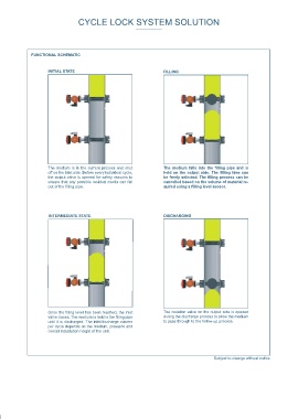
CYCLE LOCK SYSTEM SOLUTION                                                                                      CYCLE LOCK SYSTEM SOLUTION


              FUNCTIONAL SCHEMATIC                                                                                            PRODUCT SPECIFICATION
                                                                                                                                                                                 6


                     INITIAL STATE                                  FILLING                                                                     1


                                                                                                                                                                                                       6


                                                                                                                                                                    2
                                                                                                                                                                                                      5
                                                                                                                                                       SPS
                                                                                                                                                 4


                     The medium is in the current process and shut   The  medium  falls  into  the  filling  pipe  and  is                                                                                                3
                     off on the inlet side. Before every individual cycle,   held on the output side. The filling time can
                     the output valve is opened for safety reasons to   be freely selected. The filling process can be
                     ensure that any possible residual media can fall   cancelled based on the volume of material re-
                     out of the filling pipe.                       quired using a filling level sensor.


                     INTERMEDIATE STATE                             DISCHARGING                                             1. Isolation valve at input side with a pneumatic rotary actuator and stop position monitoring:
                                                                                                                            In principle, any valve – butterfly valve, gate, pinch valve or ball valve – can be used for the cycle lock. Both components (in this case butterfly
                                                                                                                            valves) are screwed together with the filling pipe in the factory. It is preferable to use single-acting (spring-reset) pneumatic actuators of type
                                                                                                                            EB-SYS for operating the valves. Stop position monitoring takes place using limit switch boxes of type SBU with mechanical or inductive limit
                                                                                                                            switches.
                                                                                                                            2. Filling pipe:
                                                                                                                            The filling pipe is used for the interim storage of the medium. Depending on the specific properties of the products to be passed through the
                                                                                                                            valve, cylindrical filling pipes are available, which can also be given different coatings. The geometry can be adapted to meet the customer‘s
                                                                                                                            specifications – for example in conical form. The chamber volume can be adapted individually.

                                                                                                                            3. Isolation valve at output side with a pneumatic rotary actuator and stop position monitoring:
                                                                                                                            The valve is screwed together with the filling pipe in the factory and automated using actuators from across the entire production program.


                                                                                                                            4. Control unit with visualisation via the touch panel:
                                                                                                                            In this example, an efficient Phönix PLC with a touch panel is used to operate and visualise the processes. It is suitable for the special challen-
                                                                                                                            ges faced in high-performance, automated processes and reliably controls dynamic applications and control-specific processes.

                     Once the filling level has been reached, the inlet   The isolation valve on the output side is opened
                     valve closes. The medium is held in the filling pipe   during the discharge process to allow the medium   5. Optional filling level sensor:
                     until it is discharged. The inlet/discharge volume   to pass through to the follow-up process.         Instead of using preset filling times, material can be passed through the valve in the volume required using a filling level sensor. The partly
                     per cycle depends on the medium, pressure and                                                          insulated measuring probe has been optimised for measuring bulk material.
                     overall installation height of the unit.
                                                                                                                            6. Optimal bypass valves:
                                                                                                                            Different pressure levels can be bridged with bypass valves. To prevent the sudden blowing out of the material in the case of a difference in
                                                                                                                            pressure between the inlet and discharge sides, pressure compensation is carried out before filling. This pressure compensation also signifi-
                                                                                                                            cantly decreases wear of the sleeve because the medium is not blown across the sleeve at a great flow velocity when opening the valve.
                                                                                         Subject to change without notice
   170   171   172   173   174   175   176   177   178   179   180