
Page 27 - Catalogue 2019
P. 27
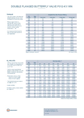
DOUBLE FLANGED BUTTERFLY VALVE F012-K1/ WN  DOUBLE FLANGED BUTTERFLY VALVE F012-K1 / WN  DOUBLE FLANGED BUTTERFLY VALVE F012-K1/ WN


 The shaft sealing of centric soft-seated butterfl y valves is primarily   TECHNICAL DATA  TORQUE  Adapted Disc Size Pressure Rating
 effected by the surface pressure between the valve disc and the   DN  Size
 liner. Especially with large nominal diameters from DN600 and high   Nominal diameter:  DN 150 - DN 2000   - The values listed in the table are  [mm]  [in]  3 bar disc  6 bar disc  10 bar disc  16 bar disc
 pressures more than 16 bar, the simple surface pressure may no   (bigger sizes upon request)    initial breakaway torques, taken   150  6  36  45  78  125
 longer be suffi cient.    with liquids and lubricant media.
 Face-to-face:  EN 558 Series 20          200       8          59            76           140            200
 EBRO  has designed  an adjustable  shaft  seal which makes it   ISO 5752 Series 20  - Please regard these as  250  10  150  180  200  240
 possible to increase the surface pressure in the shaft passage area   API 609 Table1  approximate values, as the  300  12  200  240  280  360
 so even large valves can operate at pressures of up to 25 bar.  Works standard  objective value depends on
            different factors like pressure,  350  14         350           540           610            700
 A further advantage  of this design  is that the shaft seal can be   Flange accommodation: EN 1092 PN 6/10/16  medium, rubber, quality,  400  16  420  620  750  850
 adjusted by tightening the screws and thus readjusted if necessary.  ASME Class 150  temperature ... etc.  450  18  720  746  860  1500
 AS/NZS 4087 PN 16  - Our engineers look forward to  500  20  900           1100          2255          3690
 Flange accommodation for works   help you with exact values for  600  24  1050  1800     3000          5830
 standard on request  your application.   700      28         1600          2240          3450          8100
                                          800      32         2200          3900          6600          11200
 Flange Surface Design:  EN 1092 Form A/B
 ASME RF, FF                              900      36         2800          4900          7100          14500
                                         1000      40         4800          6760          11500         24400
 Top fl ange:  EN ISO 5211                1200      48         7800         12000          21000         44000
                                         1400      48        15000         25000          40000         60000
 Marking:  EN 19                         1500      60        20000         30000          45000         75000
                                         1600      64        25000         35000          50000         90000
 Tightness check:  EN 12266 (Leakage rate A)
 ISO 5208, Kategorie 3                   1650      66        29140         40500          57000        110000
                                         1800      72        33280         46000          64000        130000
 Temperature range:  -40°C to +200°C (depending on  2000  48  38400        50000          69000        150000
 pressure, medium and material)        Bigger sizes upon request                                     All values in Nm

 Operating pressure:  16 bar (others on request)
 Adjustable bearings ensure tightness even with max. pressure loads.   Double fl anged butterfl y valve with short construction length to be
 This feature allows refi xing during operation.  used in heavy duty applications.

           K -VALUES                                                          Opening angle α°
            v
 FEATURES  - The K -value [m³ per hour] is the  DN  Size
                v
            fl ow of water at a temperature of  [mm]  [in]  20°   30°   40°    50°    60°    70°    80°     90°
 - Absolutely tight sealing with fl ow in either direction  5°C to 30°C (41°F to 86°F) at  150  6  76,5  97,3  197  375  629  957  1360  1830
 - The valve body and disc are accurately machined which results  ∆p of 1 bar  200  8  137  187  373  697  1160  1760  2510  3400
   in low operating torque and long service life and reliability  - The K -values specifi ed are  250  10  227  271  563  1090  1850  2830  4010  5390
                v
 - Triple shaft bearings prevent shaft defl ection and guarantee   based on tests carried out by the  300  12  287  409  820  1550  2610  4050  5880  8120
   optimum guidance even after many years of operating service  Delfter Hydraulics Laboratories,  350  14  399  488  1070  2110  3590  5480  7760  10400
 - Can be disassembled, material-specifi c recycling possible  the Netherlands  400  16  557  703  1360  2600  4470  7060  10400  14600
 - Single fl ange mounting is possible  - Permissible velocity of fl ow  450  18  716  907  1810  3440  5830  8980  13000  17800
 - Can be installed in any desired position  Vmax 4,5 m/s for liquids,  500  20  875  1110  2250  4280  7180  10900  15500  20900
                 Vmax 70 m/s for gases    600      24     1230  1550   3150  6010   10090  15400  21800   29400
 - Maintenance-free                       700      28     1100  1770   3590  6610   10900  16400  23200   31400
 - Fully repairable valve  - The throttle function is linear at  800  32  1670  2680  5450  10000  16500  24900  35200  47600
            an angle 30° to 70°
                                          900      36     1960  3150   6390  11800  19300  29200  41300   55900
           - Avoid cavitation            1000      40     2430  3890   7910  14600  23900  36100  51100   69100
                                         1200      48     3500  5620  11400  21000  34500  52100  73800   99800
 GENERAL APPLICATIONS  For further values, please contact
           our engineers.                1400      66     5150  8260  16780  30900  50700  76500  108000  147000
 - Offshore                              1500      60     6070  9750  19800  36400  59900  90300  128000  173000
                                         1600      64     7000  11200  22800  42000  69000  104000  148000  200000
 -Water and waste water technology
                                         1650      66     7500  12100  24500  45200  74200  112000  159000  215000
 - Shipbuilding
                                         1800      72     9430  15100  30700  56600  93000  140300  199000  269000
 - Power plants                          2000      48    11100  17900  36400  66900  110000  166000  235000  318000
                                                                                          Subject to change without notice


                                                                   post@ebro-armaturen.com
 F012-K1/ WN  1.5                                                  www.ebro-armaturen.com
                                                                   01.2019