
Page 31 - Catalogue 2019
P. 31
WAFER TYPE BUTTERFLY VALVE Z 411-A WAFER TYPE BUTTERFLY VALVE Z 411-A
TECHNICAL DATA TORQUE Adapted Disc Size Pressure Rating
da
SDR 33
SDR 11
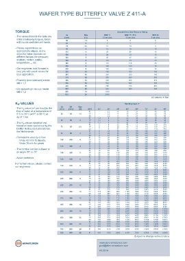
Nominal diameter: da 50 (DN 40) - da 630 (DN 600) - The values listed in the table are [mm] Size 10 bar disc SDR 17 / 17,6 6 bar disc
[in]
10 bar disc
(SDR11) initial breakaway torques, taken 50 1½ 6 6 6
with liquids and lubricant media.
2
7
7
da 50 (DN 40) - da 500 (DN 500) 63 2½ 15 15 7 9
75
(SDR17 / SDR17,6 / SDR33) - Please regard these as 90 3 18 18 10
approximate values, as the 110 4 28 28 18
Face-to-face: EN 558 Series 20 objective value depends on 125 4 28 28 18
different factors like pressure,
45
ISO 5752 Series 20 medium, rubber, quality, 140 5 6 110 45 22
160
45
78
API 609 Table 1 temperature ... etc. 180 6 110 110 45
200 8 140 140 76
Flange accommodation: EN 1092 PN 10 - Our engineers look forward to 225 8 140 140 76
help you with exact values for 250 10 200 200 180
Top fl ange: EN ISO 5211 your application. 280 10 200 200 180
315 12 220 220 200
- Powdery (non-lubricant) media 355 14 360 360 310
Marking: EN 19 Md x 1,3 400 16 620 620 540
450 20 730 730 650
Tightness check: EN 12266 (Leakage rate A) - Dry gases/high viscous media 500 20 960 960 890
ISO 5208, Category 3 Md x 1,2 560 24 1580 - -
630 24 2000 - -
Temperature range: -10°C to +160°C (depending on All values in Nm
pressure, medium and material) K -VALUES Opening angle αº
v
da DN Size
Operating pressure: max. 10 bar SDR 11,0 (PE-80) - The K -value [m³ per hour] is the [mm] [mm] [in] SDR 20° 30° 40° 50° 60° 70° 80° 90°
v
max. 10 bar SDR 17,0 (PE-100) fl ow of water at a temperature of 50 40 1½ 11 - - 2,2 8 8 15 21 33 43 50
5°C to 30°C (41°F to 86°F) at
17
21
2,2
50
33
15
43
max. 6 bar SDR 17,6 (PE-80) ∆p of 1 bar 33 - 2,2 8 15 21 33 43 50
max. 5 bar SDR 33,0 (PE-100) 63 50 2 11 1,2 8 8 13 22 38 50 65 85
38
22
50
13
17
85
65
1,2
Resilient seated, centrically mounted wafer type valve with reduced - The K -values specifi ed are 33 1,2 8 13 22 38 50 65 85
v
inside diameter for PE/PP piping systems. based on tests carried out by the 75 65 2½ 11 2 2 9 9 22 42 77 115 170 215
17
22
115
215
77
170
42
Delfter Hydraulics Laboratories, 33 2 9 22 42 77 115 170 215
the Netherlands 11 8 24 50 95 150 240 330 420
90 80 3 17 8 24 50 95 150 240 330 420
33 8 24 50 95 150 240 330 420
FEATURES - Permissible velocity of fl ow 110 100 4 11 13 28 65 130 180 340 550 800
340
130
65
28
13
180
Vmax 4,5 m/s for liquids,
800
17
550
Standard- Z 411-A 33 13 28 65 130 180 340 550 800
- Adapted butterfl y valve for PE/PP piping systems Butterfl y Valve Vmax 70 m/s for gases 125 100 4 11 13 28 65 130 180 340 550 800
340
800
13
17
130
180
65
28
550
- The disc diameter corresponds to the inside diameter of PE HD - The throttle function is linear at 33 13 28 65 130 180 340 550 800
98
950
and PP pressure pipes (SDR11 / SDR17 / SDR17,6 / SDR33) an angle 30° to 70° 140 125 5 11 19 46 130 183 272 445 720 1010
530
17
65
350
230
26
870
- Short stubs must not be removed by boring. The plant reliability 33 26 65 130 230 350 530 870 1010
11
530
26
350
130
1010
230
65
870
will not be reduced - Avoid cavitation 160 150 6 17 26 65 130 230 350 530 870 1010
- There is no need to manufacture and install complicated For further values, please contact 33 35 90 200 360 640 900 1350 2100
640
360
2100
90
35
11
1350
900
200
spacers our engineers. 180 150 6 17 35 90 200 360 640 900 1350 2100
90
900
- Can be mounted in any desired position 33 35 120 200 360 640 1100 1350 2100
2650
37
240
740
11
1870
429
200 200 8 17 37 120 240 429 740 1100 1870 2650
- Triple shaft bearings prevent shaft defl ection and guarantee 33 41 160 310 520 900 1420 2480 3390
optimum guidance even after many years of operational service 11 41 160 310 520 900 1420 2480 3390
225 200 8 17 43 180 350 580 1000 1600 3000 4000
- Interchangeable seat 33 43 180 350 580 1000 1600 3000 4000
11 43 180 350 580 1000 1600 3000 4000
- Maintenance-free 250 250 10 17 43 180 350 580 1000 1600 3000 4000
33 85 270 510 840 1410 2400 4150 5200
- Can be disassembled, material-specifi c recycling possible 11 85 270 510 840 1410 2400 4150 5200
280 250 10 17 125 360 660 1100 1800 3100 5300 6400
- For max. pressure, a through-going shaft (TS) is mounted for 33 125 360 660 1100 1800 3100 5300 6400
sizes ≥ da 400 11 133 390 710 1160 1900 3400 5500 6600
315 300 12 17 133 390 710 1160 1900 3400 5500 6600
33 170 480 870 1410 2300 4250 6650 7690
11 185 500 920 1480 2420 4500 7000 8000
GENERAL APPLICATIONS 355 350 14 17 240 610 1110 1820 3000 5750 8400 9320
33 240 610 1110 1820 3000 5750 8400 9320
9300
- Where PE/PP pipes are used 400 400 16 11 285 680 1230 2050 3400 6680 10800 10200
1400
4000
2400
11500
17
350
8000
780
33 350 780 1400 2400 4000 8000 10800 11500
11 395 870 1530 2630 4500 8900 11100 12500
450 500 20 17 395 870 1530 2630 4500 8900 11100 12500
33 480 1030 1800 3120 5500 10700 12700 16000
11 480 1030 1800 3120 5500 10700 12700 16000
500 500 20 17 500 1070 2000 3300 5900 11300 14000 18800
33 500 1070 2000 3300 5900 11300 14000 18800
560 600 24 11 540 1120 2100 3500 6300 11600 15000 21000
630 600 24 11 610 1300 2400 4100 7200 12500 17600 24000
Subject to change without notice
post@ebro-armaturen.com
Z 411-A 1.6 www.ebro-armaturen.com
01.2019