
Page 238 - Catalogue 2019
P. 238
DOUBLE CHECK VALVE DC
TECHNICAL DATA
Nominal diameter: DN 50 - DN 600
Face-to-face: EN 558-1
ISO 5752
Flange accommodation: EN 1092 PN10/16, ASME Class 150
Flange Surface Design: EN 1092 Form A/B
ASME RF, FF
Marking: EN 19
Operating pressure: 16 bar ≤ DN 250
10 bar ≥ DN 300
Tightness check: EN 12266 (Leakage Rate A)
ISO 5208, Category 3
Temperature range: 0°C to +130°C (depending on
pressure, medium and temperature)
Standard construction:
TYP DC 1 DC 2 DC 3 DC 4 DC 5
Body EN-JS EN-JS 1.4408 Alu-Bronze EN-JS
1030 1030 C954 1030
Disc Alu-Bronze 1.4408 1.4408 Alu-Bronze EN-JS
C954 C954 1030
Shafts 1.4301 1.4301 1.4404 Alu-Bronze 1.4301
C954
FEATURES Springs 1.4571 1.4571 1.4401 2.4816 1.4571
Bearing NBR EPDM EPDM NBR EPDM
- Maintenance-free wafer double check valve operating
- Can be disassembled, material-specific recycling possible
Lager PTFE PTFE PTFE PTFE PTFE
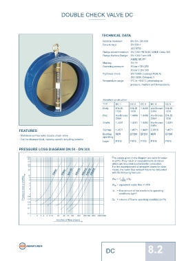
PRESSURE LOSS DIAGRAM DN 50 - DN 300
The values given in the diagram are valid for water
at 20°C. They result of measurements at valves
which are mounted in a horizontal conduction.
For the ascertainment of pressure losses for other
DN50 DN80 DN100 DN150 DN200 DN250 DN300 media, the water flow amount has to be calculated
with the following formular:
Pressure loss p (mWs) W äp = equivalent water flow in m³/h
Wäp = √
YB
x Q B
1000
YB = flow amount of the media in its operating
conditions kg/m³
Q B = volume of flow in operating condition (m³/h)
Volume of flow (I/sec)
DC 8.2